3rd party SIP device and CUCM

Adding 3rd party SIP device to CUCM is pretty straightforward: add End User with digest credentials, create SIP profile with Digest authentication support, add 3rd party SIP device (choose advanced for video) and apply config on the device itself (you should usually specify DN, end user name and digest credentials). Here is the link to cisco.com which describes the process.

But recently I encountered that my Lifesize video codec refused to register on CUCM. TCPdump showed that device sent SIP register, CUCM replied with 401 Unauthorized with all necessary info for authentication (Digest realm=”ccmsipline”, nonce=”some long random line”, algorithm=MD5), which was OK. When Lifesize calculated the response and sent it with subsequent SIP REGISTER, CUCM replied with 500 Internal Server Error:

5001

Before submitting a TAC case I decided to check device config on CUCM. There is a configuration parameter of Device Pool assigned to device. This pool define CMgroup among other things. Cisco phones download their configuration files  where they can find CUCM nodes they can register to, which is not the case with 3rd party SIP devices.

Now back to Lifesize configuration window: in SIP Registration hostname field I specified a node which was not in the CMgroup assigned to the device. When I changed it to appropriate hostname, Lifesize registered normally.

Serviceability Control Center

Recently, I’ve decided to try out CAXL IM&Presence API (https://developer.cisco.com/site/jabber-websdk/overview/overview/) and integrate a Web chat with Jabber MUCs (chat conferences). And it turns out that XCP Web connection manager which serves BOSH interface for CAXL (or jabberwerx) can’t stand more than 100 concurrent connections. This service just went to Stopped state.

While troubleshooting that with UC serviceability web interface on CUCM (like going to Cisco unified Serviceability ->  Tools -> Control center Feature services ot Network services -> choosing a node and it takes quite some time to fetch the data) I decided to write a simple GUI for this. I’ve based my server on a API’s description from here https://developer.cisco.com/site/sxml/discover/overview/service-control/.

The source is accessible from my github https://github.com/smirnov-am/cucm_srv_cc_api.

Installation should be easy: on a server with python installed, use pip to get flask and apscheduler modules and run the script. Open a browser and enter your server IP and enter srv_mon/srv_mon when it asks for credentials.

On configuration enter your CUCM and IM&P node IPs and hit Save&Run. The UCM and IMP pages should populate with service’s states:


cc

Services that are activated and not running come first, started services are just highlighted with green, inaccessible nodes and inactivated services are grey and can be found in the end of the list.

I’m going to invest some time into it later and add service stop/start/restart capabilities to it.

It looks like you can get the same info from RTMT or PrimeCollaboration which is free if you got CUWL Pro licence. But first one is slow and the latter is very greedy for computing resources and I find my solution much more helpful when debugging service states.

Problems with user login into Cisco IM&Presence

Cisco IM&Presence supports both native Cisco Jabber clients and 3rd party XMPP clients like PSI.

Cisco jabber clients use special type of DNS SRV records (_cisco-uds._tcp.example.com) which stores an address of CUCM server. When they get it they make a request to a special service called Cisco UDS for a user login and his respective parameters – Service Profile to be exact. Cisco UDS can be found in UC Serviceability in Control Center -> Network Services -> CM Services, so if you experience problems with Cisco Jabber authorization and RTMT sends you AuthenticationFailed with Interface : cucm-uds  string you can restart it.

Service Profile (CM Administration -> User Management -> User settings -> Service profile) – defines which UC services are available to a user. Navigate to End User configuration to check which service profile is tied to a certain user. Service profile have links to IM and Presence Profile, which are defined by CM Administration -> User Management -> User settings -> UC services.

It is UC services which stores addresses of IM&P nodes. That’s how Cisco Jabber clients reach IM&P and get IM capabilities. Also without _cisco-uds SRV a client queries for _cuplogin._tcp SRV which points to IM&P nodes and uses the same process as 3rd party XMPP client described below.

3rd party XMPP clients don’t use _cisco-uds SRV. They use _xmpp-client._tcp SRV which points to IM&P node. Inside IM&P there is a service of Cisco XCP Connection Manager which listens on 5222 port and provides logins. So when there is a problem with login of 3rd party XMPP client it is likely that Cisco XCP Connection Manager is faulty and should be restarted.

Cisco UDS is pretty new service and a lot of stuff relies on it now in UC infrastructure (like MRA for example – I should definetely write a post on how CIisco Jabber clients login with MRA – it’s a peice of art) and it deals with a huge load ok. But Cisco XCP Connection Manager in certain situations becomes unavailable under heavy load. From the perspective of the client it looks like it’s responding and even provides a list of possible auth mechanisms of PLAIN and CISCO_VTG_TOKEN, but returns nothing when a client send it’s encoded password with XMPP (you can observe this with PSI XML console for example).

URI dialling in UC infrastructure. Part 3.

In previous parts I’ve tried to cover the process of configuration of egress B2B URI calling. Now it’s time to set up inbound one, so your organization will have a URI in form of info@example.com and it can be dialled by outside partners. For my scheme to work you should have CUCM, a Expressway-C/E pair and Telepresence Conductor with confbridges up and running and capable of handing rendezvous conferences.
Let’s create a search rule on Expressway-E which will accept our URI and send it to Traversal zone toward Expressway-C.

34

On Expressway-C we are going to transform info@example.com on its way from Traversal Zone to 7777@cucm1.example.com and send it to Neighbor Zone pointing to CUCM

54

Assumed we have a Telepresence Conducter setup according to http://www.cisco.com/c/dam/en/us/td/docs/telepresence/infrastructure/conductor/config_guide/xc3-0_docs/TelePresence-Conductor-Unified-CM-Deployment-Guide-XC3-0.pdf
all we have to do is to create a route pattern of 7777 pointing to a SIP trunk for rendezvous conferences.

On Telepresence Conductor let’s create a separate alias of 7777 which refers to a template External B2B

123

Template External B2B should among other parameters have a pin set.

1111

So when a remote party calls you they will see a standart Cisco background with a Example.com label and will be asked to enter a PIN via DTMF.

Of course all this setup is irrelevant if you don’t have DNS SRV records for your domain visible from public Internet.

And remember all these call will requeire a RMS licences on Expressway-C/E pairs.

URI dialling in UC infrastructure. Part 2.

As soon as your endpoints – codecs and Cisco Jabber client – are registered to CUCM and ready to dial each other URIs it’s time to try dialling to an external URI,
that is outside our enterprise. External URIs could be one of the following types:
1) a normal SIP URI in a form of info@example.com where example.com domain has appropriate SRV records (_sip._udp SRV 0 5060 host.example.com. for example for SIP over UDP)
2) a SIP URI in a form of info@1.2.3.4 with an IP address in place of the domain
3) an IP address – usually guys with Polycom systems use it along with H323 protocol.
4) exotic URIs like 1.2.3.4##12345 used also by some Polycom systems – they usually can be accesses by a standard URI of 12345@1.2.3.4 or by IP 1.2.3.4

If you have only CUCM in your network you can dial only type 1 and 2. For that case you can create a SIP Route Pattern with domain routing for type1 and with IP routing with type2. I can’t definitely say why CUCM has there two flavours of SIP route patterns – my guess is that IP address notation of 192.168.0.1 can bee seen by CUCM as a domain with 4 levels and it tries an SRV lookup (for _sip._udp.192.168.0.1) instead just using this IP address for network layer.

In order to cover all possible destinations – all types of URIs and both signalling protocols – it’s better to have an Collaboration Edge servers installed. They come in two versions: VCS-E/C which supports registrations of endpoints and
Expressway-E/C which relays endpoint registrations to CUCM in case of MRA.

So, first you need a SIP route pattern *.* with domain routing in CUCM pointing to a SIP trunk (a Route list in my case as I have a clustered pair of Expressway and two SIP trunks).

1

According to this document http://www.cisco.com/c/dam/en/us/td/docs/voice_ip_comm/expressway/config_guide/X8-2/Mobile-Remote-Access-via-Expressway-Deployment-Guide-X8-2.pdf on page 30 you have to have a new  SIP Trunk Security Profile with non-standard SIP listening port for Expressway-CUCM integration to work.

This route pattern easily covers type 1 URIs. In order to dial type 2 URIs you should add a separate SIP route pattern with IP routing and specify exact IP address (and I don’t know the way to make it more flexible now).
To cover type 3 URI we will convert IP addresses to URIs with some user training and special search rules on Collaboration Edge servers.

On Expressway-C I’ve created a separate from automatically created MRA zones neighbour zone toward CUCM.

2

And configured a search rule for URI dialing. When a requests is received from CUCM Expressway-C just sends it to Traversal zone (and my traversal zone is SIP only). That shoud cover type 1 URIs

3

For dialing by IP (type 3) IP I’ve found a post http://www.ucguerrilla.com/2014/02/cisco-telepresence-endpoints-and-ip.html which suggested a using special type of URI for that.
You should instruct your users to dial 192.168.0.100@ip.local to reach external endpoint 192.168.0.100 – this effectively converts pure IP dialling to standard URI dialling.
When the request with 192.168.0.100@ip.local reaches Expressway-C the transform would convert it to IP address

4

Then for type 2 and type 3 (converted to IP address by transform)  URIs there is a separate Search rule:

6

Moreover under  Configuration -> Dial plan -> Configuration Calls to unknown IP addresses should be set to Indirect on Expressway-C for it to work.

On Internet facing Expressway-E acting as traversal server I set up a DNS zone and a search rule with pretty standard configuration.

7

9

It will deal with type 1 URIs making DNS SRV and even DNS A/AAAA lookups for H323 and SIP.

But in order to support both SIP and H32 you should have H323-SIP Interworking Gateway option key installed, and SIP-H323 interworking  turned on under Configuration -> Protocols -> interworking. And you don’t need a DNS zone for IP dialling (both type 2 and type 3) as it will be covered by option Configuration -> Dial plan -> Configuration Calls to unknown IP addresses set to direct.

URI dialling in UC infrastructure. Part 1.

URI dialling in UC infrastructure is a good thing to have for a number of reasons. For example, if your dial plan is not flexible enough and the number of digits used for DNs is insufficient to cover all endpoints. In that case moving toward URI will give you more flexibility (in case you don’t want to enable access codes).
Another reason that sounds tempting is the expansion of Cisco Jabber usage: some of my users don’t want a hardware phone any more and ask to give them the opportunity to make and receive call with Jabber only. In that case I can leave them with Directory URI only which is equal to their email, which is nice.
Moreover, URI dialling is essential when making B2B calls.
So here I’m going to cover some potential cases of URI dialling with CUCM and VCS/Expressway

1) Cisco video codecs

SX10 and SX20 codecs are very powerful devices. If they are not provisioned by CUCM or VCS they can dial via URI out-of-the-box provided SIP and H.323 protocols are on and there is no SIP proxy of H.323 gatekeeper configured.

For example, if you dial reception@example.com from a SX20 it will do the necessary DNS lookups for example.com domain and send SIP INVITE to the corresponding IP.

But in most cases codecs are managed by CUCM and all SIP INVITES are send to it. In that case you need to set up intracluster/intercluster URI dialling on CUCM and B2B dialling through collaboration edge VCS/Expressway.
I still keep H.323 protocol enabled (Configuration->System configuration->Networkservices->H323 ON) for SX20 to be capable of calling H323 destinations on its own.

2) Cisco Jabber

Jabber calling capabilities are managed and provisioned by CUCM by using special type of devices (i.e, CSF for Cisco Jabber for windows).  If you want to make calls to URI from Jabber you should enable this function in jabber-config.xml

  • download jabber-config.xml from CUCM TFTP by navigating to http://%5BIP address of CUCM node with TFTP running]:6970/jabber-config.xml
  • in the policies section change EnableSIPURIDialling parameter to true
  • upload updated jabber-config.xml to TFTP via Cisco Unified Operating System Administration -> Software updates -> TFTP File Management  -> Upload file (use / directory)
  • restart TFTP service

After restarting Cisco Jabber your devices will be able to use URIs.

3) Intracluster URI dialling
There is a document on cisco.com describing the process of enabling intracluster URIs. I want to expand it a little bit.
If you have you user account synchronized with LDAP, their URI could be imported to CUCM as a part of this synchronization. Navigate to Cisco Unified CM Administration ->End User -> select a user.
In End User Configuration window there should be a populated Directory URI filed. Then scroll down and find Directory Number Associations.

1
The drop-down Primary Extension will be populated if an end user has a control of a device with DN configured (see Device Information -> Controlled Devices in this window). So when you choose a DN user’s Direcotry URI get’s assosiated with this DN and is automatically assigned to a partition defined by  System -> Enterprise Parameters -> End User Parameters -> Directory URI Alias Partition. Be sure to add this partition to a correspondent CSS.

Another option is to define custom (up to 5 different) URIs under DN configuration.  Navigate to a device -> Association (DN association section on the left), scroll down to Directory URIs section and add one (and choose a partition). If you have already completed first option via  End User Configuration window, in that case Directory URI will show up here with a green OK sign.

2
And don’t forget to check Use Fully Qualified Domain Name in SIP Requests checkbox in all SIP profiles used by Cisco Jabber devices and codecs.

Now you can use URI for calling between Jabber and video codecs inside you CUCM cluster

4) Intercluster URI dialling
This task is accomplished with ILS,which I think deserves a separate post.

In part 2 I’m going to cover B2B URI dialling both inbound and outbound.

Ad-Hoc conferences with Cisco Telepresence

Recently I’ve been troubleshooting an issue with ad-hoc videoconferences in Cisco Telepresence.
Cisco Telepresence as described in this document http://www.cisco.com/c/dam/en/us/td/docs/telepresence/infrastructure/conductor/config_guide/xc3-0_docs/TelePresence-Conductor-Unified-CM-Deployment-Guide-XC3-0.pdf
is an infrastructure for creating ad-hoc, rendezvous and scheduled tightly coupled (that is controlled by a central call processing engine/mixer entity) conferences (opposed to loosely coupled conferences using built-in bridges).
Configuration of this system introduces a second B2B user agent – TelePresence Conductor (the first one is CallManager). Moreover, apart from communicating via SIP CallManager (CM), Conductor (TC) and Telepresence Servers (TS) (audio/video mixers themselves) communicate via XML RCP and exchange system parameters and Conference URIs.

In my setup ad-hoc conferences were shutting down in a couple of seconds after starting. So I decided to investigate how they are formed.
According to RFC 4579, when there is an active call between endpoint A and endpoint B and A wants to transfer this call into conference with endpoint C the following occur
1) While on call with B, A sends SIP INVITE to the focus (a conference mixer) with unique conference URIs
2) Focus replies with 200 OK and isfocus suffix in Contact field
3) Then after exchanging some information regarding the conference by SUBSCRIBE/NOTIFY (usually SUBSCRIBE package allows the exchange of conference names and connected parties in a form of XML) A sends SIP REFER to the focus and asks it to Refer-to B and replace B‘s calls with the new one
4) The focus replies with 202 Accepted and 100 Trying and send INVITE to B with Conference URI and asks to replace its current call with the new one.

5) The same steps are repeated for a call from A to С, thus inviting endpoint C to the same ad-hoc conference

Another way to do extend a call of A is to instruct the focus to send INVITE to B from a conference which is already started by A. This procedure can be repeated to extent this ad-hoc conference to C.

The implementation by Cisco looks like this
1) A is on a call with B. A in my case is a Cisco Jabber for Windows.
2) A wants to add a concurrent call to C to an ad-hoc conference (for A,B and C to be in one conference room)
3) A sends REFER to CM with Content-Type application/x-cisco-remotecc-request+xml which states that conference softkey was pressed and transmit A-B and A-C call IDs.
4) CM make a XML RPC (remote procedure call) to TC for a conrefence.create function and gets Conference URI.
5) CM sends in-dialog INVITE to B with delayed-offer SDP connection info 0.0.0.0 thus putting this endpoint on hold.
6) CM sends UPDATE to B with Contact parameter isfocus
7) CM sends INVITE to TC with conference URI it got from XML RPC. TC chooses available TS and relays INVITE to it. When it gets the responce from TS, TC relays it to CM
8) CM sends in-dialog INVITE to B with delayed-offer SDP connection info of TS IP thus connecting B to the mixer.
9) Asyncronously CM send INFO to B with XML which lists all connected parties with their respective Caller IDs
10) Steps from 6 to 9 are repeated for C at the same time.
11) TS periodically re-INVITES endpoint A,B,C with updated SDP if needed.

So Cisco Telepresence uses its own API to get conference URI and relies on the package application/x-cisco-remotecc-request+xml for signalling of conference start.
The issue with shutting down of ad-hoc after 10s was caused by software bug in TC, which terminated session in step 7 when KPML as a method of sending DTMF was signalled to it by CM instead of RFC2833.

PS. I’ve found a wonderful blog https://andrewjprokop.wordpress.com/ with a lot of posts describing SIP building blocks.

NAT and firewall traversal for SIP and H.323.

NAT

NAT translates the private IP addresses inside the enterprise into public IP addresses visible on the public Internet. In most cases NAT is combined with firewall into one device.

NAT is classified in two ways:

  1. mapping
  2. filtering.

NAT mapping can be endpoint independent, when it uses same external mapped address (or rather a combination of IP address and port) for packets from a device behind it, which are destined to different endpoint in the internet.

Example
Internal endpoint sends a packet with source IPi:Pi and destination IPe1:Pe1 and to destination IPe2:Pe2 (IPi – internal endpoint IP address, IPe1 and IPe2 – external endpoints #1 and #2 IP addresses, Pi, Pe2, Pe1 are correspondent transport layer ports).
NAT statically maps IPi:Pi to IPnat:Pnat in both cases, so external endpoint #1 gets a packet with source of IPnat:Pnat and destination of IPe1:Pe1 and #2
with same source of IPnat:Pnat and destination of IPe2:Pe2

In contrast there is an endpoint dependent mapping where NAT maps IPi:Pi to IPnat1:Pnat1 for endpoint #1 and  to IPnat2:Pnat2 for endpoint #2

NAT filtering can be Endpoint-independent, Address-dependent and Address- and port-dependent.
Endpoint-independent filtering allows any internal endpoint with any source port to communicate to internal endpoint once NAT binging is established by the latter.

Example
Internal endpoint send a packet with source of IPi:Pi to destination of IPe1:Pe1 to external endpoint #1.
NAT translate IPi:Pi to IPnat:Pnat. External endpoint #1 send a packet back with source of IPe1:Pe2 to NAT IPnat:Pnat and packet goes through NAT and reaches internal endpoint.
At the same time external endpoint #2 can send a packet destined to the same IP:port pair (IPnat:Pnat) and NAT would allow it to pass and eventually reach internal endpoint too.

Address-dependent filtering won’t allow this situation. It won’t let a packet from external endpoint #2 destined to IPnat:Pnat get though. However it would let external endpoint #1 to establish a new session with source of IPe1:Pe3 toward internal endpoint.
Address- and port-dependent filtering will close this breach – only one bidirectional session is allowed in this case.

Most of NAT devices are using endpoint-dependent mapping and address- and port-dependent filtering and are called symmetric NATs.

NAT complications for IP telephony.

1) External endpoint cannot connect to internal endpoint until the internal one creates a NAT binding.
2) SIP signalling carries an information of what IP address and port to use. So when lower network protocols tampers with IP address and ports SIP negotiations fails.
3) NAT bindings times out and can be restored only from behind the NAT while SIP endpoints can be both servers and client in a SIP dialog and rely on the fact that any of them can start a transmission.

Solutions

There are a number of solutions that can be applied in different situations.

NAT ALG

In addition to creating a binding NAT can inspect a call signalling and fix it appropriately. But you must be sure that your NAT device firmware is up-to-date with all signalling protocols. Moreover it cannot work with encrypted traffic so forget about secure SIP.

Rport and comedia

RFC 3581 gives support to a rport parameter in SIP Via header which instructs a remote endpoint to send signalling to destination if got from network layer.

Example
Asterisk has a a nat=force_rport and nat=comedia arguments in sip.conf which instructs it to use network layer information instead the one it got in SDP for communication with an endpoint. Comedia in this case is for media (RTP traffic) and Rport is for signalling traffic.

Straight SDP tampering

If an endpoint during its configuration knows what it’s external address would be it can construct SDP appropriately.

Example.
Asterisk has externip=XXX.XXX.XXX.XXX statement where you can define what address to use in SDP offer.

STUN

But what if you don’t know the external address, or your endpoint doesn’t allow to edit SDP like in p.3. There is STUN for it.
Internal endpoint connect via UDP 3478 to a STUN server in external network. STUN sees how internal endpoint address got transformed by NAT and inform the endpoint about it in reply. So the endpoint can implement SDP fixup with relying on this information.
But in case of symmetric NAT it won’t work because NAT mapping would be different and random when the endpoint start to communicate with another device. Moreover STUN (Simple Traversal of UDP through NAT) is for UDP and not for TCP. And SIP over TCP is more desirable in when SIP messages can be long when implementing video calling and especially video conferencing.

TURN

TURN (Traversal Using Relay NAT) server is a signalling and media relay entity situated outside the NAT in a DMZ. Once an internal endpoint connects to a TURN server it creates a binding of endpoints source address to its routeable interface and informs the endpoint about it. Then it just proxies all media and signalling traffic.
The downside of this approach might be an increased delay and an excessive load on TURN server hardware.
Now TURN is considered as a part of STUN IETF draft.

ICE

Interactive Connectivity Establishment (ICE) allows endpoints decide which address to use for communication. Endpoint are aware of their local IP address, they can get
additional candidates from STUN and TURN servers or by UPnP.

Example
When the remote endpoint receives the list in the SIP INVITE, it replies with a list of addresses obtained in a similar manner. Each endpoint proceeds to attempt connectivity to the addresses provided by the other endpoint by sending STUN messages to each address. In this mode, the endpoints themselves must implement STUN server functionality and respond to STUN request messages from the other endpoint. When an endpoint receives a STUN return message, it knows that it has found an IP address that permits connectivity. Each endpoint chooses the highest-ranked address that offers connectivity to the other endpoint. Then the SIP endpoints exchange INVITE messages again, this time using the addresses obtained during the connectivity-testing phase.

UPnP

UPnP-aware endpoints can make a request to UPnP-aware NATs to open certain pinholes or create bindings, thus making itself aware of routeable public address.
But only a few endpoints (A PC with Windows XP installed being one of them) support UPnP and even fewer NATs do that. Moreover using UPnP presents a possible security risk.

Assent and H.460

Assent is a Cisco proprietary protocol which presents a solution for NAT (and firewall) traversal for H.323 and SIP communications (both signalling and media).
H.460 is an industry standard and a successor to Assent, but is supports only H.323 while preserve the whole idea of Assent.

H.460 consists of three major parts: H.460.17 and H.460.18 for signalling and H.460.19 for media traversal.
In most cases it needs a Traversal client behind the NAT/FW and a Traversal Server in DMZ. In a case your internal endpoints support H.460 (which is rarely the case) you don’t need Traversal client.
These protocols do not need NAT ALG and require NAT to work in symmetrical mode allowing to create bidirectional pinholes.

H.460.17

This method requires a traversal client to establish a RAS tunnel to a traversal server by sending empty H.225 Transport Protocol Data Unit Packets (TPKT) or RAS rerigestrations to it.
When an internal endpoint wants to reach an external one it send signalling (RAS, H.225 and H.245) to the traversal client (a gatekeeper operating in GKRCS mode) which send them over that long-lived tunnel to the  traversal server. The same tunnel works in the opposite situation when an external endpoint send signalling to the traversal server which use the tunnel to reach
the traversal client. This tunnel needs only one 1720 port to pass through FW.

H.460.18

This one doesn’t use RAS tunnel as H.460.17. Traversal server use special H.323 RAS Service Control Indication to instruct traversal client to open a pinhole in NAT.
After that traversal client kepps the pinhole open by resending RAS RRQ reregistrations, H.225 or H.245 TPKT.
When an internal endpoint wants to reach an external one it send signalling (RAS, H.225 and H.245) to the traversal client, which relays them to traversal server in DMZ.
The traversal client then maintains NAT binding on behalf of the internal endpoint.
When an external endpoint wants to connect to an internal endpoint, the external endpoint sends a setup message to the traversal server, and then creates a RAS SCI packet that requests that the traversal client send an empty H.225 packet out through the NAT to the traversal server to open a reverse pinhole for the incoming setup message. SCI message gives the client all information about destination ports on the server. So this connection is used to transmit signalling from external endpoint to the internal one.

H.460.19

This mechanism allows traversal server to act as a media relay. It provides H.245 fixup to ensure that only routable addresses are transferred to external endpoint.
When an external endpoint wants to send media to internal network it sends media to traversal client, which in turn sends H.245 message to traversal client which instructs it to send empty RTP packet in return, so NAT binding and a pinhole are created and traversal server and client know what ports to use. H.480.19 do the same to RTCP traffic flow.

Additional feature of  H.480.19 is multiplexing, which allows traversal client to use a reduced number of port for RTP. This is done by appending a 4-byte stream number to RTP packet to identify a stream of media.

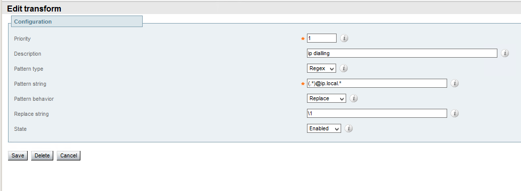
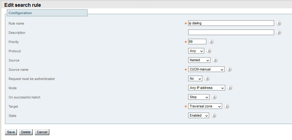
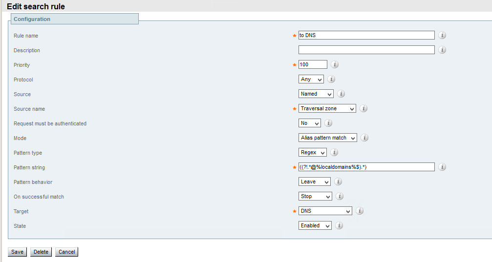
Assent protocol uses the same principles described above and allows SIP communications as well. The only product I know which implements it is Cisco Expressway
(http://www.cisco.com/c/dam/en/us/td/docs/telepresence/infrastructure/vcs/config_guide/X8-6/Cisco-VCS-Basic-Configuration-Control-with-Expressway-Deployment-Guide-X8-6.pdf)

Cisco Jabber “Share presentation” button is greyed out.

With the newest versions on CUCM and IM&Presence (10.5 and higher) greyed out “Share presentation” button in Cisco Jabber can be caused by a couple of things:
a) “Allow BFCP” checkbox isn’t checked in SIP profile of the CFS (TAB,BOT,TCT) device in CUCM
b) firewall is blocking a connection.
When investigating the latter I decided to discover what is this BFCP and how the presentation is shared.

1) When I make a call from Cisco Jabber to another video-capable endpoint (i.e SX20), a SIP invite is sent with following SDP attributes

Media Description, name and address (m): video 25990 RTP/AVP 126 97
Media Attribute (a): content:main

Media Description, name and address (m): video 26744 RTP/AVP 126 97
Media Attribute (a): content:slides

Media Description, name and address (m): application 5316 UDP/BFCP *
Media Attribute (a): floorctrl:c-s

Attribute with content:main describes our main video stream. The RTP stream will start right after called endpoint answers.
Attribute with content:slides is a presentation stream. This stream will be a usual RTP carrying payload with type of 126 (H264 coded video). It won’t start until we hit “Share presentation” button.
Attribute with application 5316 UDP/BFCP is a description of BFCP protocol. According to https://tools.ietf.org/html/rfc4582 it controls who is holding a shared resource (presentation in our case) and who’s transmitting (to avoid bidirectional presentation sharing).
Import thing here is who is going to be the server in this connection. In my case floorctrl:c-s shows that Jabber is willing to be a server as well as a client.

2) Let’s look at the SIP 200OK with SDP

Media Description, name and address (m): video 16880 RTP/AVP 126
Media Attribute (a): content:main

Media Description, name and address (m): video 16882 RTP/AVP 126
Media Attribute (a): content:slides

Media Description, name and address (m): application 28339 UDP/BFCP *
Media Attribute (a): floorctrl:c-only

First 2 media descriptions are obvious: they are usual answers to offers of the calling party. But in application 28339 UDP/BFCP there is an attribute of floorctrl:c-only.
This shows that called party is going to be a client in BFCP terms. Moreover it will initiate a BFCP connection. If there is a firewall which block UDP port 5316 in direction from endpoint to Jabber, BFCP server in Jabber won’t see an incoming connection and would grey-out the button. This BFCP connection will occur right after SIP 200 Ok and long before you can hit a “Share presentation” button in Cisco Jabber.

3) This only describes a case when you share the presentation during a call.
In addition you can share presentation without making a call from a chat window in Jabber. This is done without BFCP with a different protocol.

How to start a Web-server with nginx+uwsgi+flask

The fastest way of providing a web interface to your Python project is, in my opinion, to use Flask (http://flask.pocoo.org/). But it’s built-in web server is good only for testing and development (in my case I’ve got some strange errors like broken pipes when I tried to put in production under moderate load). So the recommended option is to use nginx and uwsgi as a web server and flash as a backend.
1) In case of a fresh installation of Ubunty 14.04 first thing you should do is to install some packages: pip for installation of usefull Python modules, python-dev in order to enable pip to install uwsgi and nginx

sudo apt-get update
sudo apt-get install python-pip python-dev nginx

2)    Let’s also install virtualenv. Ubunty Trusty comes with python 2.7.6 which lacks ssl library. My previous idea was to install python 2.7.9 into separate directory and to use it, but later I found cool molude named requests (http://docs.python-requests.org/en/latest/) which deal with all ssl stuff, so now I’d rather use systemwide python. But in order to isolate it from other admins who like to mess with python modules it’s better to use  virtualenv

sudo pip install virtualenv

3)    Now let’s create our projects directories

sudo mkdir /opt/my_flask
cd /opt/my_flask

4)    We will store our virtualized python here with a command

sudo virtualenv my_flask_env

5)    Now we have to activate it

sudo source my_flask_env /bin/activate

And the prompt would look like:

(my_flask_env)user@host:/opt my_flask$

6)    Install flask and uwsgi

sudo pip install uwsgi flask

7)    Create a sample application with flask

sudo vi /opt/my_flask/my_flask.py

Here we need to import Flask module and create a route of / which will return HTML code when requested

from flask import Flask
application = Flask(__name__)

@application.route("/")
def hello():
    return "<span>Hello world!</span>"

if __name__ == "__main__":
    application.run(host='0.0.0.0')

8)    Now we have to create uwsgi entry point, which will link uwsgi with our flaks application

sudo vi /opt/my_flask/wsgi.py
from my_flask import application

if __name__ == "__main__":
    application.run()

9)    It’s time to make a configuration file for uwsgi

sudo vi /opt/my_flask/my_flask.ini
[uwsgi]
socket = /tmp/uwsgi.sock
module = my_flask
callable = application
enable-threads = true
chmod-socket = 666
vacuum = true
die-on-term = true
req-logger = file:/tmp/reqlog
logger = file:/tmp/errlog

/tmp/uwsgi.sock – is a special socket used as a pipe between nginx and uwsgi process and uses special uwsgi protocol.

die-on-term – will help to start and stop our process with init scripts,

vacuum is needed for socket clean up

10)    Now let’s create an upstart script and a separate user

sudo useradd --no-create-home nginx
sudo vi /etc/init/my_flask.conf
description "uWSGI server of my_flask"
start on runlevel [2345]
stop on runlevel [!2345]
setuid nginx
setgid www-data
env PATH=/opt/my_flask/my_flask_env/bin
chdir /opt/my_flask
exec uwsgi --ini my_flask.ini

11)    Starting uwsgi is simple – just type

sudo start myproject

12)    Now let’s configure nginx to connect to the socket

sudo vi /etc/nginx/sites-available/default

And inside server block paste this

server {
    listen 80;
    server_name server_domain_or_IP;

    location / {
        include uwsgi_params;
        uwsgi_pass unix=:/tmp/uwsgi.sock
    }
}

13)Restart nginx with

sudo service nginx restart

And that’s it. Navigate to http://server_domain_or_IP and I’ll be able to see Hello world!
You can aslo find all logs in /tmp/reqlog and /tmp/errlog