3rd party SIP device and CUCM

Adding 3rd party SIP device to CUCM is pretty straightforward: add End User with digest credentials, create SIP profile with Digest authentication support, add 3rd party SIP device (choose advanced for video) and apply config on the device itself (you should usually specify DN, end user name and digest credentials). Here is the link to cisco.com which describes the process.

But recently I encountered that my Lifesize video codec refused to register on CUCM. TCPdump showed that device sent SIP register, CUCM replied with 401 Unauthorized with all necessary info for authentication (Digest realm=”ccmsipline”, nonce=”some long random line”, algorithm=MD5), which was OK. When Lifesize calculated the response and sent it with subsequent SIP REGISTER, CUCM replied with 500 Internal Server Error:

5001

Before submitting a TAC case I decided to check device config on CUCM. There is a configuration parameter of Device Pool assigned to device. This pool define CMgroup among other things. Cisco phones download their configuration files  where they can find CUCM nodes they can register to, which is not the case with 3rd party SIP devices.

Now back to Lifesize configuration window: in SIP Registration hostname field I specified a node which was not in the CMgroup assigned to the device. When I changed it to appropriate hostname, Lifesize registered normally.

URI dialling in UC infrastructure. Part 2.

As soon as your endpoints – codecs and Cisco Jabber client – are registered to CUCM and ready to dial each other URIs it’s time to try dialling to an external URI,
that is outside our enterprise. External URIs could be one of the following types:
1) a normal SIP URI in a form of info@example.com where example.com domain has appropriate SRV records (_sip._udp SRV 0 5060 host.example.com. for example for SIP over UDP)
2) a SIP URI in a form of info@1.2.3.4 with an IP address in place of the domain
3) an IP address – usually guys with Polycom systems use it along with H323 protocol.
4) exotic URIs like 1.2.3.4##12345 used also by some Polycom systems – they usually can be accesses by a standard URI of 12345@1.2.3.4 or by IP 1.2.3.4

If you have only CUCM in your network you can dial only type 1 and 2. For that case you can create a SIP Route Pattern with domain routing for type1 and with IP routing with type2. I can’t definitely say why CUCM has there two flavours of SIP route patterns – my guess is that IP address notation of 192.168.0.1 can bee seen by CUCM as a domain with 4 levels and it tries an SRV lookup (for _sip._udp.192.168.0.1) instead just using this IP address for network layer.

In order to cover all possible destinations – all types of URIs and both signalling protocols – it’s better to have an Collaboration Edge servers installed. They come in two versions: VCS-E/C which supports registrations of endpoints and
Expressway-E/C which relays endpoint registrations to CUCM in case of MRA.

So, first you need a SIP route pattern *.* with domain routing in CUCM pointing to a SIP trunk (a Route list in my case as I have a clustered pair of Expressway and two SIP trunks).

1

According to this document http://www.cisco.com/c/dam/en/us/td/docs/voice_ip_comm/expressway/config_guide/X8-2/Mobile-Remote-Access-via-Expressway-Deployment-Guide-X8-2.pdf on page 30 you have to have a new  SIP Trunk Security Profile with non-standard SIP listening port for Expressway-CUCM integration to work.

This route pattern easily covers type 1 URIs. In order to dial type 2 URIs you should add a separate SIP route pattern with IP routing and specify exact IP address (and I don’t know the way to make it more flexible now).
To cover type 3 URI we will convert IP addresses to URIs with some user training and special search rules on Collaboration Edge servers.

On Expressway-C I’ve created a separate from automatically created MRA zones neighbour zone toward CUCM.

2

And configured a search rule for URI dialing. When a requests is received from CUCM Expressway-C just sends it to Traversal zone (and my traversal zone is SIP only). That shoud cover type 1 URIs

3

For dialing by IP (type 3) IP I’ve found a post http://www.ucguerrilla.com/2014/02/cisco-telepresence-endpoints-and-ip.html which suggested a using special type of URI for that.
You should instruct your users to dial 192.168.0.100@ip.local to reach external endpoint 192.168.0.100 – this effectively converts pure IP dialling to standard URI dialling.
When the request with 192.168.0.100@ip.local reaches Expressway-C the transform would convert it to IP address

4

Then for type 2 and type 3 (converted to IP address by transform)  URIs there is a separate Search rule:

6

Moreover under  Configuration -> Dial plan -> Configuration Calls to unknown IP addresses should be set to Indirect on Expressway-C for it to work.

On Internet facing Expressway-E acting as traversal server I set up a DNS zone and a search rule with pretty standard configuration.

7

9

It will deal with type 1 URIs making DNS SRV and even DNS A/AAAA lookups for H323 and SIP.

But in order to support both SIP and H32 you should have H323-SIP Interworking Gateway option key installed, and SIP-H323 interworking  turned on under Configuration -> Protocols -> interworking. And you don’t need a DNS zone for IP dialling (both type 2 and type 3) as it will be covered by option Configuration -> Dial plan -> Configuration Calls to unknown IP addresses set to direct.

URI dialling in UC infrastructure. Part 1.

URI dialling in UC infrastructure is a good thing to have for a number of reasons. For example, if your dial plan is not flexible enough and the number of digits used for DNs is insufficient to cover all endpoints. In that case moving toward URI will give you more flexibility (in case you don’t want to enable access codes).
Another reason that sounds tempting is the expansion of Cisco Jabber usage: some of my users don’t want a hardware phone any more and ask to give them the opportunity to make and receive call with Jabber only. In that case I can leave them with Directory URI only which is equal to their email, which is nice.
Moreover, URI dialling is essential when making B2B calls.
So here I’m going to cover some potential cases of URI dialling with CUCM and VCS/Expressway

1) Cisco video codecs

SX10 and SX20 codecs are very powerful devices. If they are not provisioned by CUCM or VCS they can dial via URI out-of-the-box provided SIP and H.323 protocols are on and there is no SIP proxy of H.323 gatekeeper configured.

For example, if you dial reception@example.com from a SX20 it will do the necessary DNS lookups for example.com domain and send SIP INVITE to the corresponding IP.

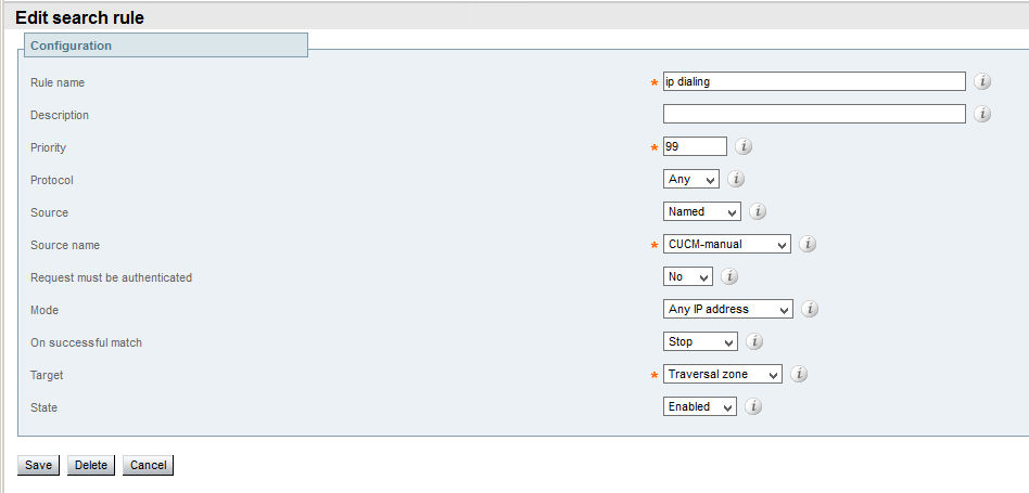
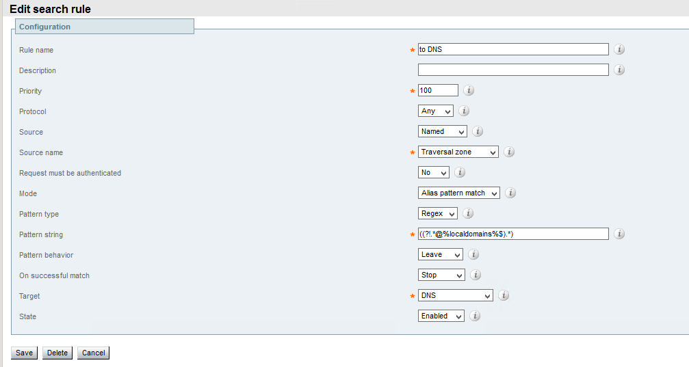
But in most cases codecs are managed by CUCM and all SIP INVITES are send to it. In that case you need to set up intracluster/intercluster URI dialling on CUCM and B2B dialling through collaboration edge VCS/Expressway.
I still keep H.323 protocol enabled (Configuration->System configuration->Networkservices->H323 ON) for SX20 to be capable of calling H323 destinations on its own.

2) Cisco Jabber

Jabber calling capabilities are managed and provisioned by CUCM by using special type of devices (i.e, CSF for Cisco Jabber for windows).  If you want to make calls to URI from Jabber you should enable this function in jabber-config.xml

  • download jabber-config.xml from CUCM TFTP by navigating to http://%5BIP address of CUCM node with TFTP running]:6970/jabber-config.xml
  • in the policies section change EnableSIPURIDialling parameter to true
  • upload updated jabber-config.xml to TFTP via Cisco Unified Operating System Administration -> Software updates -> TFTP File Management  -> Upload file (use / directory)
  • restart TFTP service

After restarting Cisco Jabber your devices will be able to use URIs.

3) Intracluster URI dialling
There is a document on cisco.com describing the process of enabling intracluster URIs. I want to expand it a little bit.
If you have you user account synchronized with LDAP, their URI could be imported to CUCM as a part of this synchronization. Navigate to Cisco Unified CM Administration ->End User -> select a user.
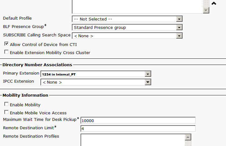
In End User Configuration window there should be a populated Directory URI filed. Then scroll down and find Directory Number Associations.

1
The drop-down Primary Extension will be populated if an end user has a control of a device with DN configured (see Device Information -> Controlled Devices in this window). So when you choose a DN user’s Direcotry URI get’s assosiated with this DN and is automatically assigned to a partition defined by  System -> Enterprise Parameters -> End User Parameters -> Directory URI Alias Partition. Be sure to add this partition to a correspondent CSS.

Another option is to define custom (up to 5 different) URIs under DN configuration.  Navigate to a device -> Association (DN association section on the left), scroll down to Directory URIs section and add one (and choose a partition). If you have already completed first option via  End User Configuration window, in that case Directory URI will show up here with a green OK sign.

2
And don’t forget to check Use Fully Qualified Domain Name in SIP Requests checkbox in all SIP profiles used by Cisco Jabber devices and codecs.

Now you can use URI for calling between Jabber and video codecs inside you CUCM cluster

4) Intercluster URI dialling
This task is accomplished with ILS,which I think deserves a separate post.

In part 2 I’m going to cover B2B URI dialling both inbound and outbound.

Ad-Hoc conferences with Cisco Telepresence

Recently I’ve been troubleshooting an issue with ad-hoc videoconferences in Cisco Telepresence.
Cisco Telepresence as described in this document http://www.cisco.com/c/dam/en/us/td/docs/telepresence/infrastructure/conductor/config_guide/xc3-0_docs/TelePresence-Conductor-Unified-CM-Deployment-Guide-XC3-0.pdf
is an infrastructure for creating ad-hoc, rendezvous and scheduled tightly coupled (that is controlled by a central call processing engine/mixer entity) conferences (opposed to loosely coupled conferences using built-in bridges).
Configuration of this system introduces a second B2B user agent – TelePresence Conductor (the first one is CallManager). Moreover, apart from communicating via SIP CallManager (CM), Conductor (TC) and Telepresence Servers (TS) (audio/video mixers themselves) communicate via XML RCP and exchange system parameters and Conference URIs.

In my setup ad-hoc conferences were shutting down in a couple of seconds after starting. So I decided to investigate how they are formed.
According to RFC 4579, when there is an active call between endpoint A and endpoint B and A wants to transfer this call into conference with endpoint C the following occur
1) While on call with B, A sends SIP INVITE to the focus (a conference mixer) with unique conference URIs
2) Focus replies with 200 OK and isfocus suffix in Contact field
3) Then after exchanging some information regarding the conference by SUBSCRIBE/NOTIFY (usually SUBSCRIBE package allows the exchange of conference names and connected parties in a form of XML) A sends SIP REFER to the focus and asks it to Refer-to B and replace B‘s calls with the new one
4) The focus replies with 202 Accepted and 100 Trying and send INVITE to B with Conference URI and asks to replace its current call with the new one.

5) The same steps are repeated for a call from A to С, thus inviting endpoint C to the same ad-hoc conference

Another way to do extend a call of A is to instruct the focus to send INVITE to B from a conference which is already started by A. This procedure can be repeated to extent this ad-hoc conference to C.

The implementation by Cisco looks like this
1) A is on a call with B. A in my case is a Cisco Jabber for Windows.
2) A wants to add a concurrent call to C to an ad-hoc conference (for A,B and C to be in one conference room)
3) A sends REFER to CM with Content-Type application/x-cisco-remotecc-request+xml which states that conference softkey was pressed and transmit A-B and A-C call IDs.
4) CM make a XML RPC (remote procedure call) to TC for a conrefence.create function and gets Conference URI.
5) CM sends in-dialog INVITE to B with delayed-offer SDP connection info 0.0.0.0 thus putting this endpoint on hold.
6) CM sends UPDATE to B with Contact parameter isfocus
7) CM sends INVITE to TC with conference URI it got from XML RPC. TC chooses available TS and relays INVITE to it. When it gets the responce from TS, TC relays it to CM
8) CM sends in-dialog INVITE to B with delayed-offer SDP connection info of TS IP thus connecting B to the mixer.
9) Asyncronously CM send INFO to B with XML which lists all connected parties with their respective Caller IDs
10) Steps from 6 to 9 are repeated for C at the same time.
11) TS periodically re-INVITES endpoint A,B,C with updated SDP if needed.

So Cisco Telepresence uses its own API to get conference URI and relies on the package application/x-cisco-remotecc-request+xml for signalling of conference start.
The issue with shutting down of ad-hoc after 10s was caused by software bug in TC, which terminated session in step 7 when KPML as a method of sending DTMF was signalled to it by CM instead of RFC2833.

PS. I’ve found a wonderful blog https://andrewjprokop.wordpress.com/ with a lot of posts describing SIP building blocks.